The first analysis consisted in the organization and planning of the work and the related analysis of the problems to solve.
CAD modelling with CATIA
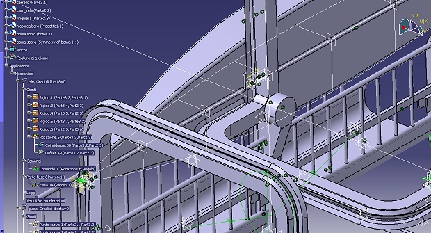
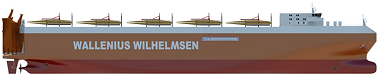
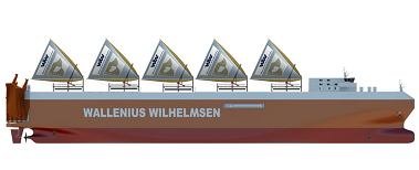
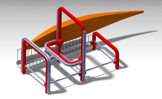
We modellized the module with CATIA. Since we did not know exactly the dimensions of the parts, we estimated them, keeping in consideration the dimensions of the ships where the modules have to be implemented. The following are simulations of the modules mounted on a commercial vessel. Below there is an example of ship specifications.
We estimated the main structure to be rectangular on the base, with one side double the size of the other, considering 8 meters for the shortest.
Guide modelling
The rail guides allow the movements of the bogies and therefore of the booms. Moreover they support them during operations.
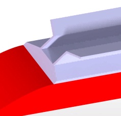
The best way to assure the movement seems to be by means of cables on the fixed guide and by means of a on-site motor on the moving guides that allow the bogies to 'climb' the guides regardless of their movement: the active boom (the one that moves) bogie would stay on the 'L' shape structure guide, while the other (the lower one) would stay still on the fixed one.
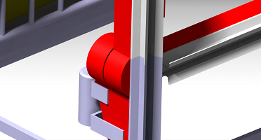
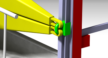
A key feature of our project is the fact that the movement of the upper boom is only given by the moving of the motorized bogie climbing the guide, while the 'L' would move accordingly. In this way, we only need 4 motors:
- The fixed motor on the base that assure the movement of the bogie on the fixed guide by means of a cable.
- The fixed motor (visible in the images above) that allow the 'L' shape structure to rotate and switch between the two main sequences (described below)
- 2 motors on the booms to allow them to 'climb' the moving guides.
Bogie design
The bogie is a key part since it sustains all the stresses coming from the wind power. This feature allow the booms to move on the guides when necessary, but for most of the time bogies would stay still. In fact, movements are necessary just once every several days on average.
This is the reason why it has been necessary to think about a passive locking system that allows to keep the bogies still and firm without the need for energy.
We decided to study the bogie on the big still arc, that is the one moved by cables. In this device the locking system is critical, because there are no motors on-site. In order not to include another motor just to unlock the system, we tried to use the tension of the cable. The following is a sketch of the mechanism:
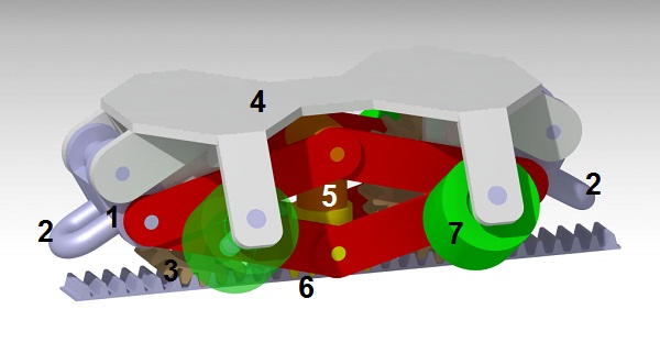
In grey and beige there are the bogie body and the two gear wheels attached (4 and 3) and, below, the gear guide. The cable responsible for the movement of the bogie is attached in 2 to its supports (1). The supports can rotate, but only towards outside directions (away from the central spring). The spring (5) preload forces down the locking cogs (6) to remain fixed on the guide's gauge line, and therefore make the bogie to remain still. The four wheels in green (7) keep the bogie attached to the guide blocking vertical movements and give stability in lateral directions.
When a tension on the cable occur on one side (i.e. the motor is activated) the cable support (1) tends to rotate and therefore to compress the spring and lift the locking. Once the locking is lifted, the bogie is free to move until the motor stops. The spring assure that the bogie would be locked again.
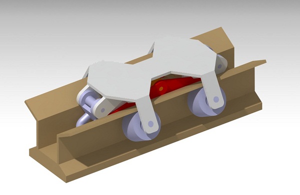
Here's a render with the bogie in the rectilinear guide:
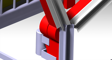
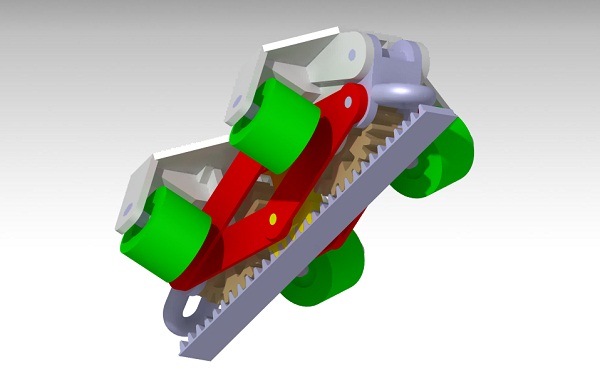
We also studied the case of the curved guide. In this case the bogie is always in motion, so the locking cogs are always up and do not interfere with the gauge line. The shape of the bogie has been designed to avoid interferences also on the upper part. Here's a render showing the most critical position:
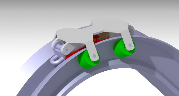
The force needed to raise the booms (tension of the cable) is 95kN. The kinematics of the bogie imposes a ratio between the forces: in initial condition (bogie locked) the force needed to make the equilibrium is about 40kN. In the final configuration the force applied to the spring is 23kN, therefore the spring in final configuration has to develop a force that is lower. Moreover, when compressed, the spring length decrease of 50mm, and the possible maximum diameter is 140mm. We choose a spring with a characteristic of 200 N/mm and a preload compression of 50mm.
In the moving guide ('L' structure) the motors perform the locking and unlocking operations.
Kinematics
The proper movement of the structure is the most tricky part of the project.
The sail movements can be divided into two main sequences: the hoisting, that is the raising of the sail, and the tacking, that is the movement that allow the sail to be opened on the opposite side. The two movements both use the 'L' shape structure: in the first case, its aim is to sustain the superior boom, in the latter, it make up the second symmetrical guide to allow the sliding of bogies to the opposite side. The two sequences are shown in the following animations:
The movement of the bogie is whown in the following video.