Designing parametric spur gear and the involute curve
First of all, while designing Parts, spur gears are only a representation of overall dimensions, as it is for threaded bolts.
Nevertheless, in order to produce beautiful Parts, we have decided to design also an approximation of involute curve.
In this section we want to explain how we have designed parametric a spur gear (20 teeth, modulus = 10 and pressure angle = 20deg) with CATIA V5 ®.
The involute curve is designed starting from the base circle using a spline curve defined by points which are calculated by Lewis Equation. The spline itself is then mirrored on a plane. The external profile is obtained by the outside circle, while the internal one is obtained by the root whose radius is shorter than the base circle radius. For this reason, the conjunction between the spline and the root is obtained by an extrapolation from the spline itself. In the end, a circular pattern designs the entire profile of spur gear.
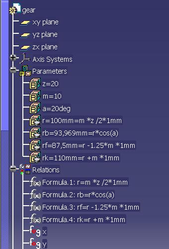
1. PARAMETERS AND FORMULAS
The whole gear is controlled by the following parameters:
- a: the pressure angle [deg];
- m: the modulus [millimetre];
- z: the number of teeth [integer].
- rb: base circle radius [millimetre]
- r: pitch circle radius [millimetre]
- rk: outside circle radius [millimetre]
- rf: root radius [millimetre]
| r | m * z / 2 |
| rb | r * cos(a) |
| rf | r - 1,25 * m |
| rk | r + m |
You have to start Generative and Shape Design and enter previous Parameters and Relations in the "Formulas" window and in "Formula Editor" one.
The involute curve is obtained by a spline through 6 points calculated by Lewis' Law: you have to enter a law for x coordinate of the involute curve and another one for y coordinate. These are the laws entered:
x = rb * sin(t * PI * 1rad) - rb * t * PI * cos(t * PI * 1rad)
y = rb * cos(t * PI * 1rad) + rb * t * PI * sin(t * PI * 1rad)
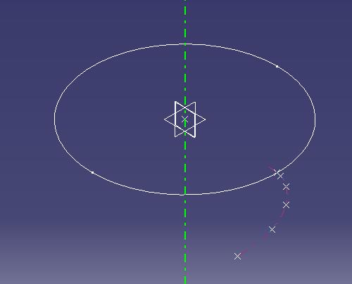
These laws are f(t) and t is a real parameter 0≤t≤1 This is what we have obtained so far:
2. MAKING THE GEOMETRIC PROFILE
Once defined the laws, you have to design 6 points on xy plane whose Horizontal and Vertical coordinates are an evaluation of x and y in 0, 0.1, 0.2, 0.3, 0.4, 0.5. Then you have to design a spline curve defined by Point.1 - Point.6. After having designed a circle with radius rb, you can make an Extrapolation from the spline whose length is ( rb - rf ) * 1.5. In this picture you can see the base circle, Point.1 - Point.6 and the involute curve (spline + extrapolation, pink).
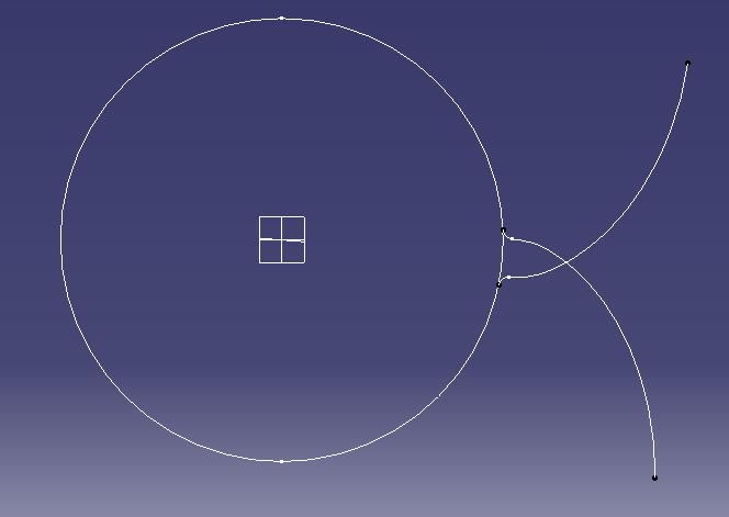
You have to create the rf circle and you have to define a corner between the root and the involute curve: its radius is m * 0.38 according to the normative formula. Now you have to mirror the half-profile you have just designed: to do this you have to trim the profile and to define the median plane of the tooth as a plane with an offset from yz plane of inv(360 / z) / 4 and a rotation axis Z Axis. This is what you see:
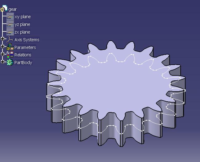
To complete our profile, you have to draw the outside circle (radius rk), to trim useless curves, to insert a circular pattern and to trim again till you obtain the profile of the spur gear. If you extrude this profile, this is what you can see (white: profile)
PLEASE NOTE:
- For this section only, you can visit these sources, credits and links:
http://gtrebaol.free.fr/
http://www.rcub.bg.ac.yu/~ggajic/pub/catia/gear/ - This is not a step-by-step guide, this only an indication about how we have designed gears.