
Dynamic Analysis
The dynamic simulation, done in Autodesk Inventor, has been utilized mainly for two porpuse:
• evaluate points of interest where high concentration of stress can be found
• verify the kinematic behaviour of the system in function of imposed dynamic of the hook, in particular evaluate driving force
necessary to allow the system to work nominally, while remaining coherent to the CEI 60335 standard
The system composed by the case, hook and cam has two degree of freedom: the horizontal traslation of the hook and the rotation of the cam. Inside the software, the doorlock has been constraned even more, for analysis sake, by imposing a kinematic bond of sliding between hook and cam.
From these considerations two kinds of simulation were derived:
1) To verify the kinematic behaviour of the doorlock the residual degree of freedom has been constrained by imposing a constant force of 50 N on the hook
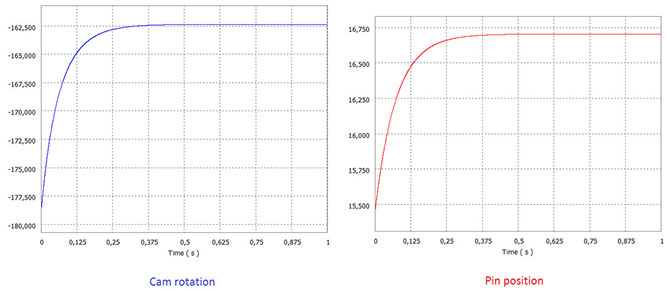
(Graphics of cam rotation and pin position)
From the diagrams it can be seen that by applying a 50 N force, imposed by the norm, the positions of cam and pin stabilizes at constant values after a time interval equal to 5 seconds. We can conclude that the design is coherent with the CEI 60335 norm
2) The evaluation of the points of interest has been done by constrainig the last degree of freedom through the imposition of the movement of the hook in function of time. By doing this we tried to simulate the insertion and extraction of the hook in the case by a user, all in a time interval equal to 1 second
Driving force of the hook in extraction and instertion in the case, kinematic imposed:
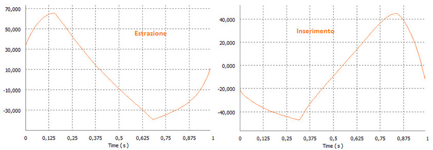
(Force in extraction and insertion)
From this analysis we can noticed how the forces at play are below 73 N in extraction and 46 N in insertion, at this magnitude the doorlock can be used by all kind of user and sufficient to garantee that the system doesn't change its configuration due to random events, for example the slamming of the dryer's door.
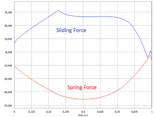
(Sliding froce between cam and hook, elastic force in insertion, kinematic imposed)
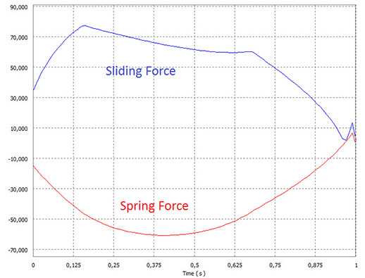
(Sliding froce between cam and hook, elastic force in insertion, kinematic imposed)
The analysis of the two graphs allowed us to determine 4 critical cases to further study inside a FEM simulation: when the spring force and sliding force are maximum, both in extraction and in insertion.
Laboratorio Progettuale CAD - Academic year 2015-2016