
CAD modeling
CAD modeling of the necessary parts for the realization of the door lock has been performed in observance of the constraints provided by Rold srl about the size and the overall dimensions of the system.
The decision of modeling software ended up choosing Inventor, mainly for the fact that, unlike Catia, this program allowed us to carry out the dynamic verification of the parts, once these were completed.
The most important constraint has been placed on the pin, for which, since provided by third parts, it was preferable not to change any of its specifications. Given the absence of original technical drawings of the single parts, the dimensions have been obtained through measurements carried out with the callipers.
(CAD model of the pin, the same of the current device)
The Blocking Cam
Subsequently the modeling activities focused on the blocking cam and the support.
Blocking cam design started by the drawing of the front profile, that is the surface which, in contact with the pin, would have to ensure the proper functioning of the mechanism. For this reason, since the pin and blocking cam are designed to work in contact with one another, the profile has been effectively "calculated" to ensure a drive force required by the user equal to 43 N for the closing of the door lock.
The front of the blocking cam is designed to resist, due to its robustness, the contact forces exerted by the pin, for which the mass was concentrated at the points where typically develop the most significant contact forces.
The optimization
Afterwards, always keeping in mind the constraints imposed by the type of material used for the blocking cam (yield strength, elastic modulus) and by the technological cycle necessary for the manufacturing of the system, it has been carried on a topological optimization in order to minimize the amount of material used in the production of the blocking cam.
The results of this operation were analyzed accurately to verify that the required product properties were not altered with respect to the design specifications established; However, as a result of the optimization, in spite of a small material saving, there has been a remarkable decrease of the safety factor (2 to 1.4) which was far from the recommended value in the design phase.
For this reason it has been preferred the optimization of the blocking cam without the aid of a specific software (Inspire), so that this process could be controlled by us more closely, in order to avoid that the project parameters could be significantly modified.
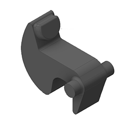
(Initial CAD model of the blocking cam)
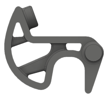
(CAD model of the blocking cam, optimized wiht Altair Inspire)
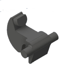
(Final CAD model of the blocking cam)
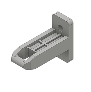
The support
The next step regarded the support; this has been modeled with particular attention to maintaining the overall dimensions of the one currently in production.
Obviously, its internal architecture has been modified significantly in order to allow the positioning of the new mechanism, in particular to ensure that the adopted spring could work in the range of length between free length condition and maximum compression in operation (values provided by the manufacturer's catalog).
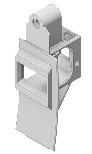
(CAD model of the Support)
The assembly
The last operation in the modeling phase regarded the assembly.
The single parts were bound to one another in such a way that the only degrees of freedom allowed to the entire mechanism were the straight movement of the pin inside the support and the rotation of the blocking cam around its hinge due to the contact with the pin. The kinematic of the door lock system was eventually verified by the analysis tools provided by the modeling software.
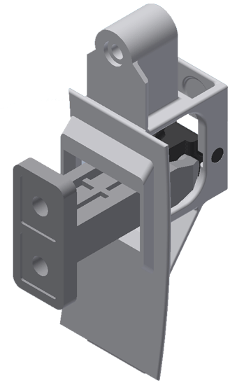
(CAD assembly of the Doorlock)
Laboratorio Progettuale CAD - Academic year 2015-2016